Click here for MegaSquirt® MegaManual™ Information, Guides, and Links

MicroTCU™ - QuickStart Guide      


Differences Between MShift™ on MicroTCU™ and GPIO Controllers

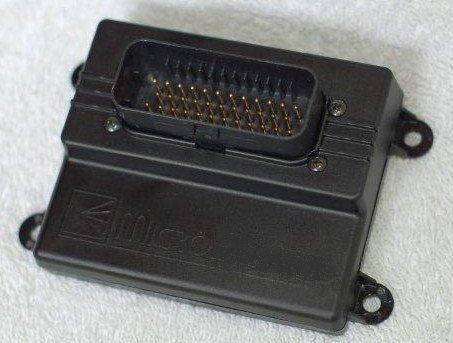
Your microTCU™ transmission controller has some hardware differences compared to a GPIO based controller. These differences depend to some degree on how the GPIO board is built. This document summarizes the differences and similarities between the microTCU™ controller and MShift™/GPIO controller with a standard build.

  1. The microTCU™ controller will work for virtually any transmission that a standard build of the GPIO board will work on. It has all the hardware capabilities, nothing has been omitted in the new design (subject to thorough testing, of course). The microTCU™ controller runs the same MShift™ code as the GPIO boards runs. The SMD board has up to 7 shift solenoid controls (8 with the beta code), up to 8 forward speeds (plus PNR), switchable shift tables, etc. So microTCU™ is still a 'universal' transmission controller.

  2. The microTCU™ Ampseal pin assignments have changed somewhat from the GPIO pin out. This was necessary to make the SMD PCB layout as clean, free of interference, and compact as possible while brining additional circuits out through the Ampseal connector. Power is still on pin #1, and grounds are on pin 19 and 20. The microTCU™ controller pin assignments are:
    microTCU™
    Pin
    Use
    Notes
    Equivalent
    GPIO
    Pin
    1V12_RAWPower in.1
    2VSS+2
    3BRKBrake input (set active high or active low in software).3
    4Paddle DOWNManual downshift button (ground to shift).4
    5Input4Can be used as 2WD/4WD - table switch.5
    6Input26
    7LED27
    8LED38
    9LED49
    10LED110
    11Spare Port 111
    12Output4/Spare Port 212
    13CANH13
    14ISS+14
    15Paddle UPManual upshift button (ground to shift).15
    16CANL16
    17BOOTLBootloader. Ground while cycling power to load new code.Separate header for bootloader on GPIO board, pin #17 is a sensor ground on the GPIO board.
    18ISS-Input shaft sensor ground for MAX9926.No ISS- on GPIO board. Pin #18 is a ground on the GPIO board.
    19GND19
    20GND20
    21Serial Rx21
    22Serial Tx22
    23Output123
    24Load24
    25Input 325
    26Input 126
    27Line Pressure Input27
    28VSS-Vehicle speed sensor ground for MAX9926.VSS- goes to pin #17 on GPIO board. Pin #28 is 5Vref on the GPIO board.
    291AMPOne amp constant current supply for pressure control solenoid.Not available on the GPIO board. Pin #29 on the GPIO board is connected to VR4, which is not used on the standard GPIO build.
    30Temperature Input30
    31Speedo OutCan be used as spare port 0. Requires external transistor for devices capable of flowing more than 200 milliamps.31
    32TCC32
    33PC33
    34Output 334
    35Output 235

  3. Shift solenoid outputs 1, 2, 3, and 4; and the outputs for PC, TCC, and Spare Port 1 are capable of up to 4 Amps continuous current.

  4. The LED circuits are nominally designed to drive LED or a 7-segment display (at less than 1/10 Amp), BUT they could be used for device control purposes if the user chooses. The microTCU™ LED driver hardware is designed to handle up to 3 Amps per LED, which should be enough for many devices (and users can use an external driver if required for devices that flow more than that).

  5. The microTCU™ speedo output (which can also be used as spare port 0) is designed to handle up to 200 milliamps. Its primary purpose is for signalling, but it can be used as a shift solenoid control - in which case it would most likely need to be used to control a larger external transistor.

  6. The microTCU™ controller supplies a nominal one-amp constant current (0.95 to 1.06 Amps in practice) for a PWM'd line pressure control valve. This makes pulse width modulation (PWM) of the pressure control valve much more stable and predictable over varying supply voltages and pulse widths (this is how it is done from the factory on GM's 4L60e and 4L80e transmissions). This circuit is not on the GPIO board.

  7. Inputs 1, 2, and 3 are designed to be used as either digital or analog inputs (selectable in software) with no changes to the hardware.

  8. 5Vref is not brought out on the microTCU™ Ampseal connector. It would have been nice to do, but there just aren't enough pins left; and 5V is only needed for certain external load sensors (MAP, MAF or TPS) when not using the CAN capabilities, and this is often available from another controller (or easily created with a 7805 voltage regulator).

  9. The VSS and ISS signals for the microTCU™ controller are now conditioned with a MAX9926 integrated circuit rather than with discrete components. This required dedicated ground pins for the sensors.

  10. The serial connections on the microTCU™ controller come out the Ampseal on pins 21 (Rx) and 22 (Tx). There is no provision for a 3.5mm jack mounted directly on the PCB.

  11. The microTCU™ board has a user cut-able trace in series with the CAN termination resistor, in the event this is not the only CAN node in the system.

  12. The microTCU™ PE0 CPU pin is not used. It has no functions in the MShift™ transmission code at all. It was brought out on the GPIO board, but because it can be used only as an input it is somewhat less useful than most of the other pins.

Enjoy driving your microTCU™ controller equipped vehicle! If you have any questions or problems, you can:

you can ask questions at the MicroTCU™ support forum which is at: www.microTCU.com


MegaSquirt®, MicroSquirt®, and MicroTCU™ controllers are experimental devices intended for educational purposes.
MegaSquirt®, MicroSquirt®, and MicroTCU™ controllers are not for sale or use on pollution controlled vehicles. Check the laws that apply in your locality to determine if using a MicroSquirt® or MicroTCU® controller is legal for your application.
©2013 Bruce Bowling and Al Grippo. All rights reserved. MicroSquirt® and MicroSquirt® are registered trademarks. This document is solely for the support of MicroSquirt® boards from Bowling and Grippo.